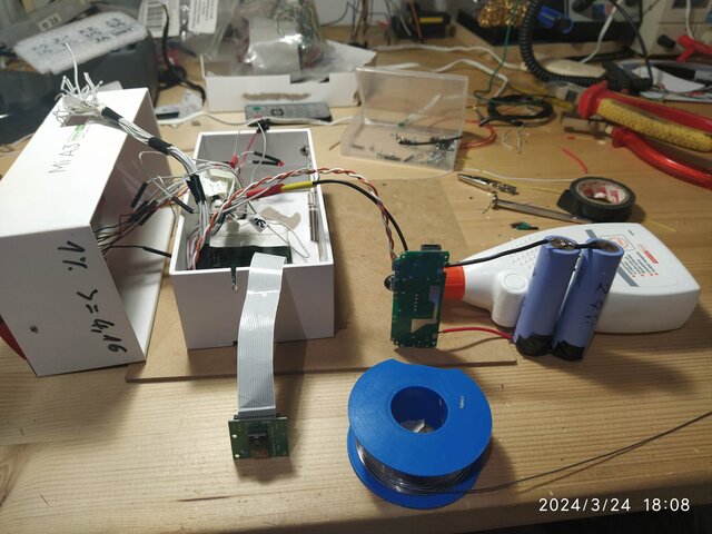
Working under tight constraints.
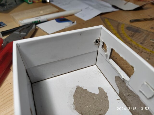
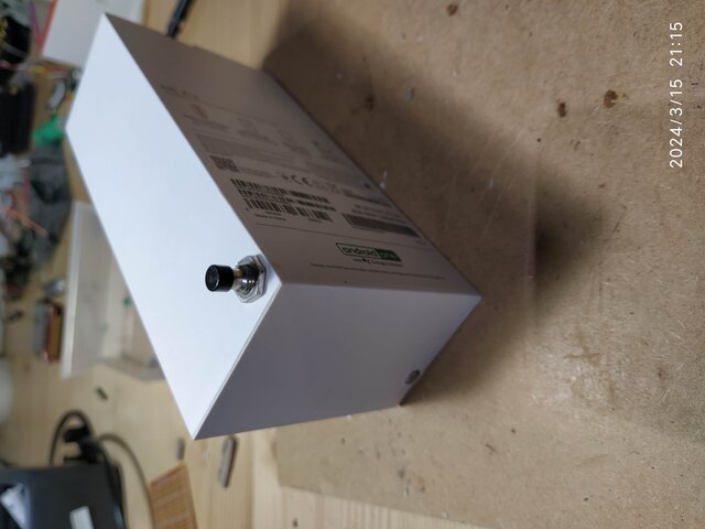
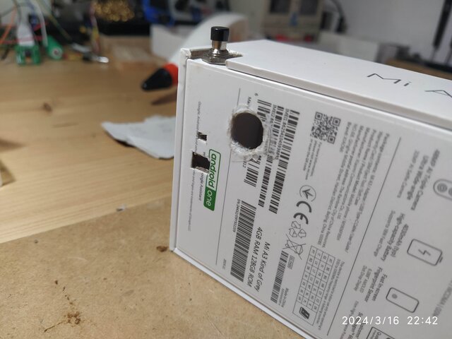
Considerable effort was required to integrate a metal piece as the button head for the loading-step-up board.
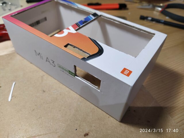
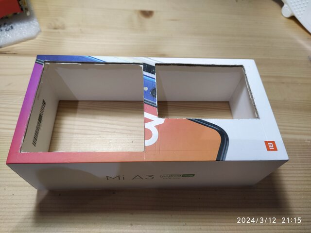
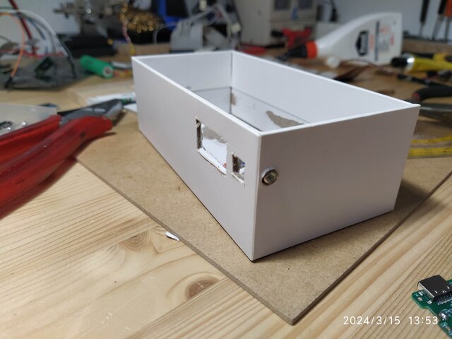
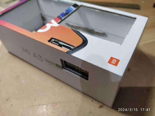
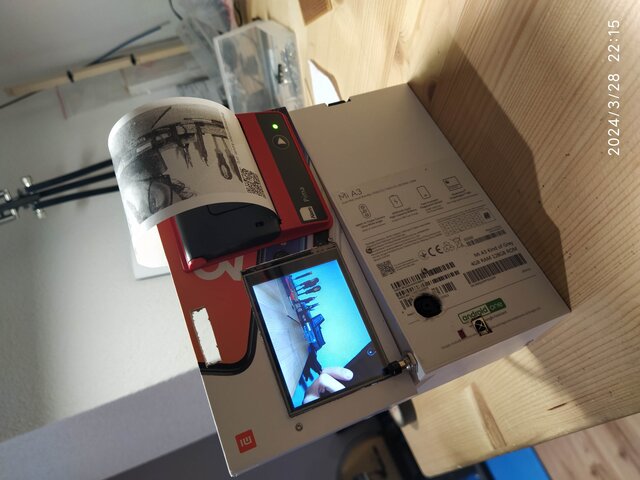
Creating openings for the charging adaptors.
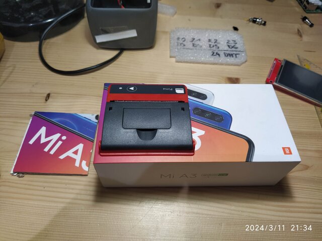
Implementing a button for capturing pictures.
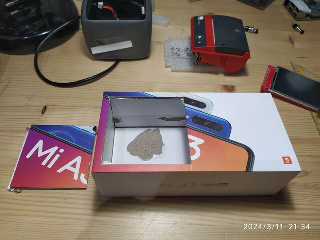
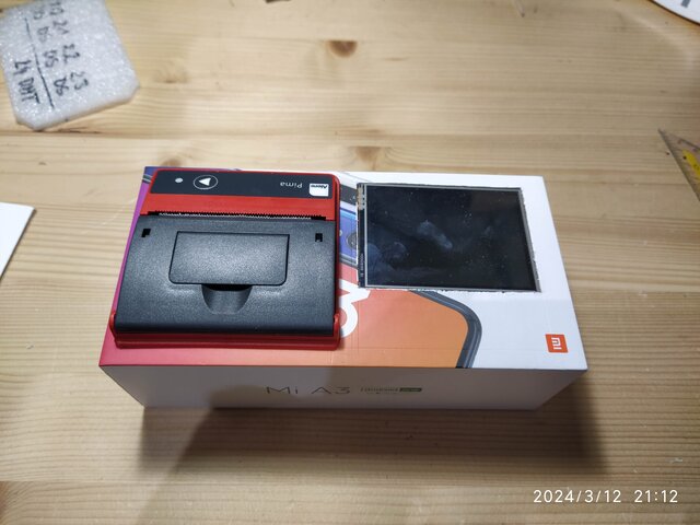
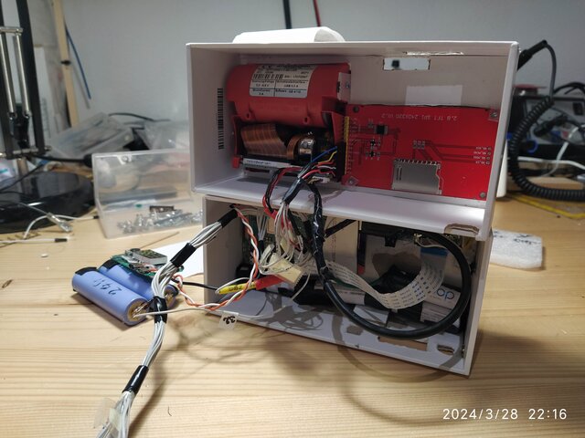
Ensuring the camera remains internally elevated to prevent it from protruding beyond the case.
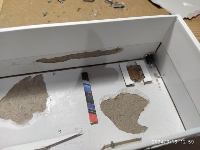
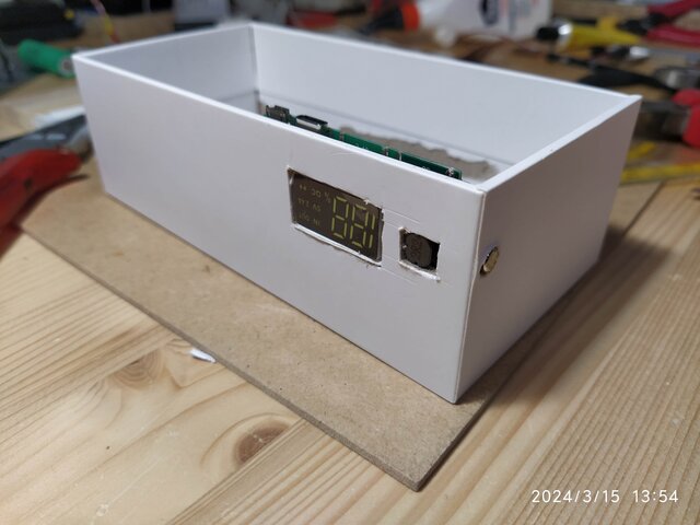
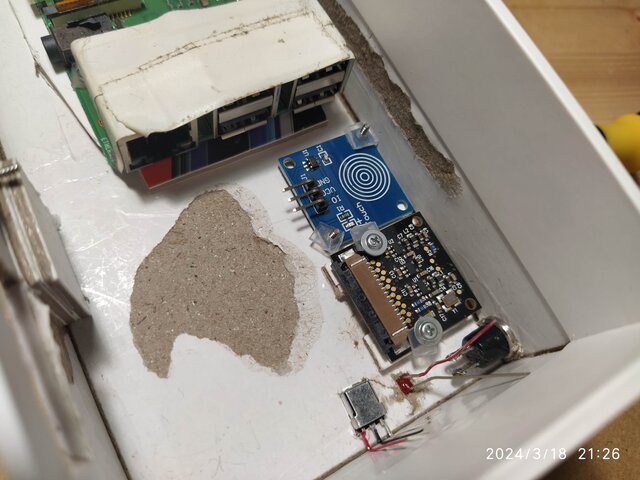
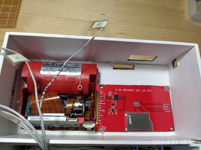
Designing openings for the camera, IR sensor, and shutter LED.
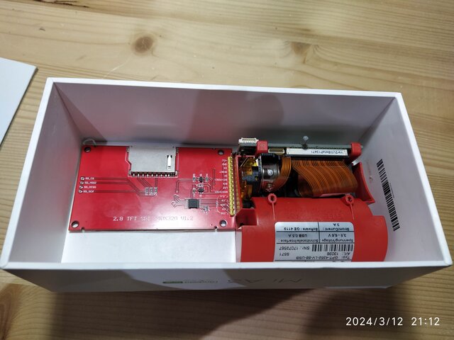
Mounting the first electronics and circuits using screws salvaged from old CD-ROMs.
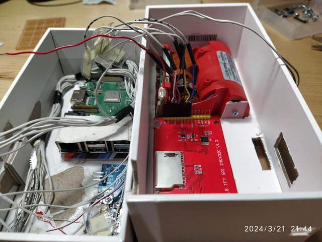
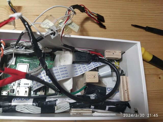
Utilizing an old IDE Hard Disk connector.
Crafting plastic bolts to mount the TFT screen.
Adapting connectors from an obsolete computer case.
Soldering the shutter button, IR remote, and shutter LED.
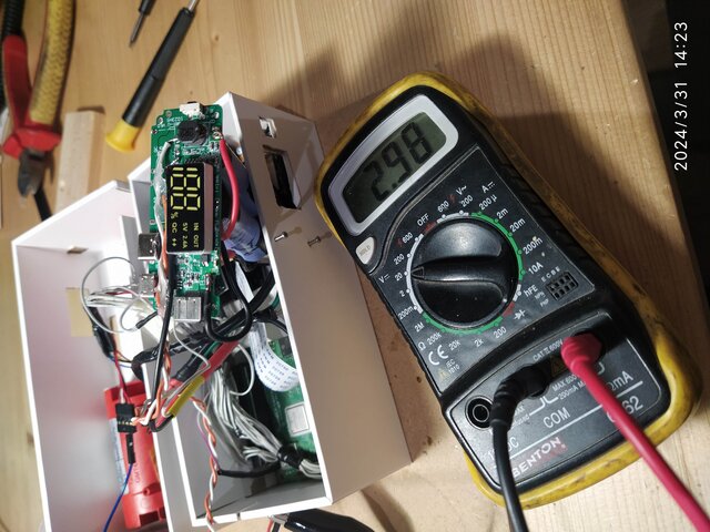
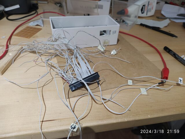
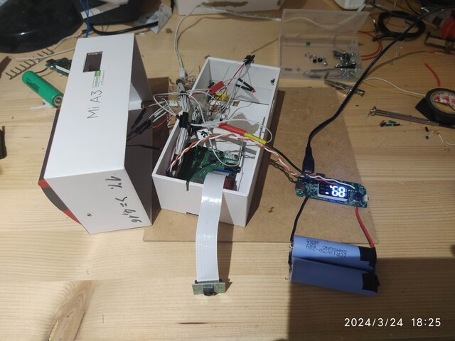
However, there are issues with undervoltage once again. I suspect the thin IDE40 wires are incapable of carrying sufficient current to the Raspi. Thus, I've removed the first four pinholes from the connector, based on previous successful tests.
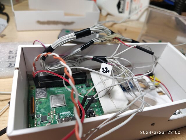
I've resoldered the wires, connecting all GND-GPIO pins for ground, and pin 2 and pin 4 for VCC. Additionally, a new loading-step-up board with two Li-ion cells has been installed.
I used glue to mount the ir-sensor and the flusher LED.
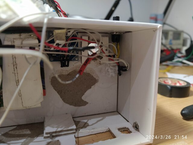
I soldered the cells of the printer together and glued them with hot-glue into the ground of the case.
Today i shortended the printer USB-cable and tested the printing function if it cause an undervoltage situation. NO! It works perfect.
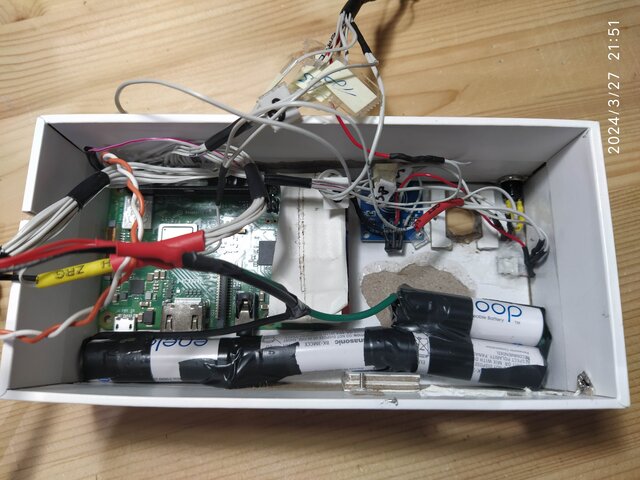
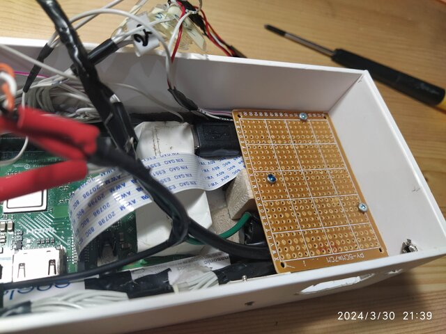
Building the holder plate for the Li-Ion-Cells.
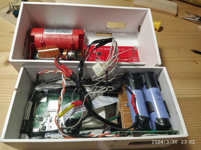
Then i discovered a problem, if i switch the powerbank-board off, i have an open circuit voltage of 3V. I also tested this with a second-powerbank board and its the same. I am thinking to mount a security switch between board and cells, if the cam is laying around longer useless, the cells could be drained empty.