Raspbian Bullseye OS
I have installed Bullseye Lite.
Command in the terminal: sudo dd if=bullseye_lite.img of=/dev/sda bs=1M status=progress.
Before removing the card for safety, execute sync in the terminal.
To find out whether you have a 32-bit or 64-bit OS, the following command in the terminal helps: getconf LONG_BIT
You can find the manually installed packages and the python installed modules/packages in a txt file in the github repo.
apt-mark showmanual > installed_packages_showmanual_20240303.txt
pip freeze > python_pip_installed.txt
Settings in /boot/config.txt
dtoverlay=gpio-shutdown
dtparam=audio=on
dtoverlay=gpio-ir,gpio_pin=7

hdmi_force_hotplug=1
hdmi_group=2
hdmi_mode=87
hdmi_cvt=320 240 60 1 0 0 0
dtoverlay=ov5647
dtoverlay=vc4-fkms-v3d #braucht die picame bibliothek für den preview
max_framebuffers=2
disable_overscan=1

[cm4]
otg_mode=1

[all]

[pi4]
arm_boost=1

[all]
gpu_mem=128
/boot/cmdline.txt
console=serial0,115200 console=tty1 root=PARTUUID=35c18dd5-02 rootfstype=ext4 fsck.repair=yes rootwait
/etc/rc.local
- simple method to set a GPIO status after boot without additional software
echo "10" > /sys/class/gpio/export
sleep 0.1
echo "out" > /sys/class/gpio/gpio10/direction
echo "1" > /sys/class/gpio/gpio10/value
sleep 0.1

ir-keytable -a /etc/rc_maps.cfg -s rc0 & # remotecontrol
sudo /home/pi/fbcp-ili9341/build/fbcp-ili9341 & # framebuffer copy for TFT
/usr/bin/python /home/pi/picamera/cam.py & # cam control script
/sbin/iw dev wlan0 set power_save off & # poweroff wifi
ir remote configs
- dvbt_01
[[protocols]]
name = "dvbt_01"
protocol = "nec"
variant = "nec32"

[protocols.scancodes]
0x8012 = "KEY_POWER"
0x8001 = "KEY_MUTE"
0x801a = "KEY_VOLUMEUP"
0x8002 = "KEY_VOLUMEDOWN"
0x801e = "KEY_UP"
0x8003 = "KEY_DOWN"
0x8004 = "KEY_1"
0x8005 = "KEY_2"
0x8006 = "KEY_3"
0x8007 = "KEY_4"
0x8008 = "KEY_5"
0x8009 = "KEY_6"
0x800a = "KEY_7"
0x801b = "KEY_8"
0x801f = "KEY_9"
0x800d = "KEY_0"
0x800c = "KEY_ZOOM"
0x800e = "KEY_EQUAL"
- dvbt_02
[[protocols]]
name = "dvbt_02"
protocol = "nec"
variant = "nec32"

[protocols.scancodes]
0x40 = "KEY_CAMERA"
0x4d = "KEY_POWER"
0x54 = "KEY_ADDRESSBOOK"
0x16 = "KEY_MUTE"
0x4c = "KEY_RECORD"
0x05 = "KEY_CHANNELUP"
0x0c = "KEY_TIME"
0x0a = "KEY_VOLUMEDOWN"
0x1e = "KEY_VOLUMEUP"
0x12 = "KEY_0"
0x02 = "KEY_CHANNELDOWN"
0x1c = "KEY_DIRECTION"
0x09 = "KEY_1"
0x1d = "KEY_2"
0x1f = "KEY_3"
0x0d = "KEY_4"
0x19 = "KEY_5"
0x1b = "KEY_6"
0x11 = "KEY_7"
0x15 = "KEY_8"
0x17 = "KEY_9"
TFT driver for framebuffer
Since the internal software for the Raspi camera is fixed on fb0 (framebuffer0) and HDMI coded, there is no other option than copying fb0 to fb1 (framebuffer1=TFT). For this, there is a separate project that I use and compile.
- To make it work, you need to configure an overlay in /boot/config.txt.
- However, this is a special overlay (basically a driver) that needs to be compiled by yourself, as detailed in this repository.
- The pin numbers in the CMake configuration are the GPIO numbers.
- CMake settings for use with Raspi2:
## fro raspi  000e and 000f revision = first gen raspis
cmake -DILI9341=ON -DGPIO_TFT_DATA_CONTROL=24 -DGPIO_TFT_RESET_PIN=25 -DGPIO_TFT_BACKLIGHT=23 -DSPI_BUS_CLOCK_DIVISOR=8 -DSINGLE_CORE_BOARD=ON -DARMV6Z=ON -DDISPLAY_ROTATE_180_DEGREES=ON ..

## raspi 3b revision and a02082 revision
cmake -DILI9341=ON -DGPIO_TFT_DATA_CONTROL=24 -DGPIO_TFT_RESET_PIN=25 -DGPIO_TFT_BACKLIGHT=23 -DSPI_BUS_CLOCK_DIVISOR=16 -DARMV8A=ON -DDISPLAY_ROTATE_180_DEGREES=ON -DSTATISTICS=0 ..

make -j
WIFI
I want my WIFI to always be turned on so that my phone doesn't turn off the hotspot. Here are the instructions for that: Turn off WIFI powersave
WIFI wpa_supplicant
Webserver Setup for Photo Uploads
- Create a CNAME entry in DNS management.
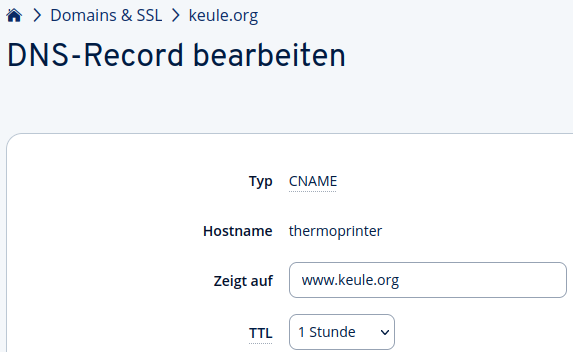
- Add an nginx config under
/etc/nginx/sites-available. - Generate SSL keys:
sudo certbot --nginx -d thermoprinter.keule.org - Test the configuration:
sudo nginx -t - Reload nginx:
sudo systemctl reload nginx - Upload images to the server
Arduino
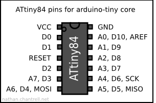
I manage the Li-Ion cell voltage monitoring using a small ATTiny84A (of which I have several). These were my requirements:
- I want to see if the battery needs recharging during operation and also when shut down.
- This means there is always 5V available for the Arduino.
- A red LED should light up (labeled "charge").
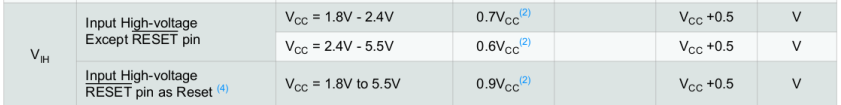
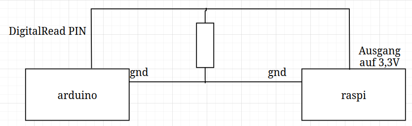
- It would be clean with level adjustment; Raspi provides 3.3V, and for the ATTiny84A, a minimum of 0.6VCC (=3V) is needed to recognize as HIGH, but it alos work without. I dont needed to use a lelvelshifter.
- Arduino must read GPIO whether Raspi is running or not.
- Voltage when Raspi is not running -> less than 3.7V -> red LED lights up
- Voltage when Raspi is running -> less than 3.5V -> red LED lights up
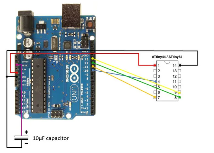
The guide Arduino UNO as Programmer helped me. What I didn't know was that you need your own libraries for the tinys and they are not installed by default.
My config in the Arduino IDE:
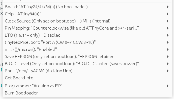
Possibly useful for debugging: Serial Output via UNO Programmer